DTU BTech 1st Year BEE Unit 1 Important Questions 2026DC Circuits & Network Theorems – Solved Numericals, Reported Repeated Questions & Formula Sheet
For DTU B.Tech 1st year students: Basic Electrical Engineering (BEE) is one of the first core subjects a B.Tech student meets, and its numerical problems can seem daunting at first. Once the fundamentals are clear, however, it becomes one of the most scoring papers. This article covers Unit 1 (DC circuits and network theorems) step by step, with solved examples and exam guidance.
PKBy Parth Khurana•Updated •Daily Spark••36 min read
Depending on the university, this subject appears as BEEE (Basic Electrical and Electronics Engineering) or BEE (Basic Electrical Engineering). The name and the unit structure differ from one university to another, so check them in your own syllabus.
In most syllabi the first few units are similar: DC circuits, AC circuits and three-phase systems, with BEEE typically adding an electronics section at the end. A student need not worry that the subject name differs from another university's. This article focuses on Unit 1 (DC circuits and network theorems) of the DTU syllabus.
2First, the Basics: Series and Parallel
This is the foundation of the subject. Once series and parallel are clear, every later chapter becomes easier.
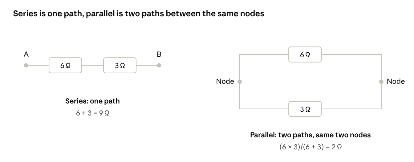
Recognising a series connection: When resistors are connected one after another on a single path, they are in series. In series you simply add them. For example, 6 Ω and 3 Ω in series give R_{eq} = 9\ \Omega.
Recognising a parallel connection: When resistors are on separate paths, side by side, and both of them start and end at the same points.
Using nodes to spot parallel connections: A point where three or more wires meet is a junction (principal node). Strictly, any point where two or more elements connect is a node, but only junctions matter for nodal analysis and for spotting parallel connections. Resistors are in parallel only when both of their ends connect to the same two nodes; resistors that merely leave one node on different paths (as in a star connection) are not necessarily in parallel. Where only two wires meet, there is no junction, and the two resistors are in series.
Figure 1 · Series vs parallel circuit · 6 Ω and 3 ΩIn the left circuit the current has one path; on the right it splits at a node, so the two resistors are in parallel.
Two ways to find the equivalent resistance of parallel resistors:
Product-over-sum method: multiply the two resistances and divide by their sum. For 2 and 4 Ω: \frac{2 \times 4}{2 + 4} = \frac{8}{6} = \frac{4}{3} = 1.33\ \Omega.
Reciprocal method: add the reciprocals, then take the reciprocal of the result.
Solved example: The 6 Ω and 3 Ω resistors meet at a common node, so they are in parallel. The resulting 2 Ω is in parallel with the 5 Ω resistor, and the remaining 18 Ω and 8 Ω resistors are in series with that result. Redrawing the circuit after every step is a useful habit: even the largest network can be reduced by starting from the innermost combination and simplifying one piece at a time.
practice matters, and the real skill is observation: identifying which resistors are in series and which are in parallel. A scientific calculator (fx-991 type) saves considerable time on simultaneous equations. Where calculators are not permitted, the equations must be solved by hand, using elimination or substitution.
3DTU BEE Unit 1 Syllabus 2026
Unit 1 has three parts: Mesh Analysis, Nodal Analysis and Theorems. Syllabus topics can change between sessions, so confirm the current list on the official DTU website.
Going by the pattern in previous years' papers, a question from Mesh or Nodal analysis is very likely.
Going by the same pattern, at least one question on theorems is usually asked in a paper.
The theorems are Thevenin, Norton, Maximum Power Transfer and Superposition. Thevenin, Norton and Max Power are interlinked. Superposition is also commonly asked. Tellegen's theorem is in the syllabus but has been asked only rarely in previous years. It can still appear as a surprise question, since many students skip it. Reciprocity, source transformation and star-delta conversion are also covered later in this article (Sections 8 and 9); check your syllabus to see whether they are examinable.
The derivation of Maximum Power Transfer can be asked; the derivation of Tellegen's theorem rarely.
These frequencies are trends from previous years' papers, not a guarantee, so always check the latest syllabus and the previous-year papers of your own session. The sections below take them one at a time.
4Mesh Analysis Numericals with Solutions (Loop vs Mesh)
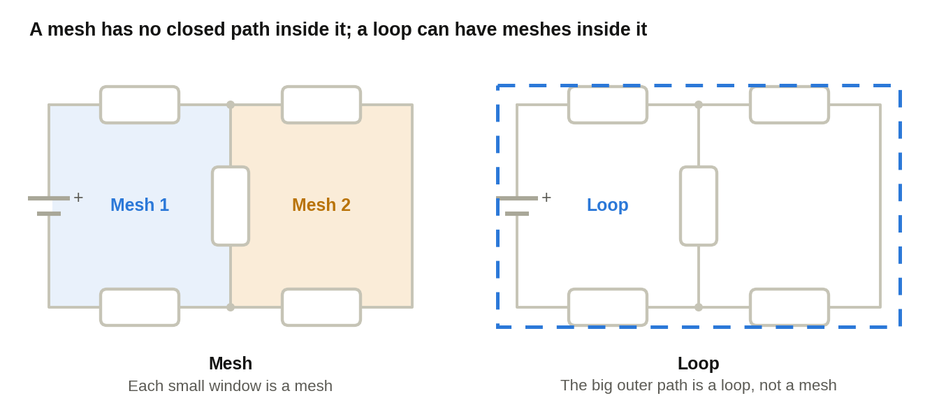
Mesh vs Loop: A mesh is a closed path that has no other closed path inside it. A loop can have closed paths inside it. For example, if a diagram has two small windows, each small window is a separate mesh, while the big outer path is a loop (not a mesh). In mesh analysis, only the smallest closed paths are used.
Figure 2 · Mesh vs loop · two windows and one outer pathMesh 1 and Mesh 2 are the two smallest windows. The dashed outer path encloses both of them, so it is a loop and not a mesh.
Mesh analysis always uses KVL (Kirchhoff's Voltage Law). (Nodal analysis uses KCL, which comes later.)
KVL can be stated simply as: the sum of all voltage drops equals the sum of all EMFs. Voltage drops are found using Ohm's law (V = I \times R).
\sum V_{drop} = \sum\text{EMF}\quad\quad V = I \times R
Step-by-step method to write mesh equations
Assign a current to every mesh (I_{1}, I_{2}, ...). Use the same direction (clockwise or anticlockwise) for all meshes.
While traversing a mesh, for a resistor belonging only to that mesh, write I \times R with its own mesh current.
For a resistor common to two meshes, write your own mesh current minus the other mesh's current. For example, if the common resistor in Mesh 1 is 3 Ω, write 3\left( I_{1} - I_{2} \right), and in Mesh 2 write 3\left( I_{2} - I_{1} \right).
Source sign: while walking, if you come out of a battery from its long (plus) terminal, take the EMF as positive; if you come out from the short (minus) terminal, take it as negative. Follow one convention throughout (both the first-sign and the second-sign conventions are valid, but they must not be mixed).
Write one equation per mesh and solve the equations simultaneously (the equation mode of a scientific calculator handles two or three unknowns).
The 3 types of mesh problems
Type 1: Only voltage sources and resistances. Apply KVL directly.
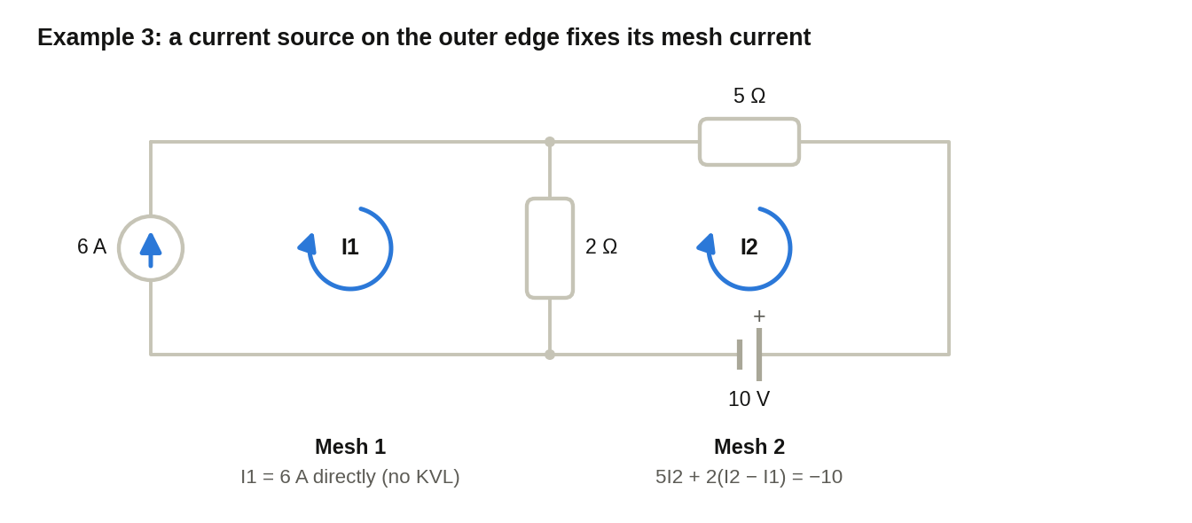
Type 2: Voltage sources, resistances and a current source on the outside (on the edge). The mesh current of that mesh is directly equal to the current source value (plus if the direction is the same, minus if opposite). No KVL is needed for that mesh.
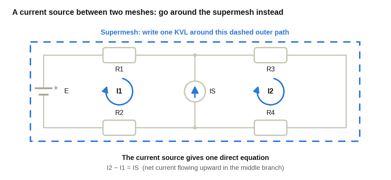
Type 3 (Supermesh): The current source lies between two meshes (internal). That is why it is called a supermesh.
Solved example 1 (Type 1): find the current in the 1 Ω resistor
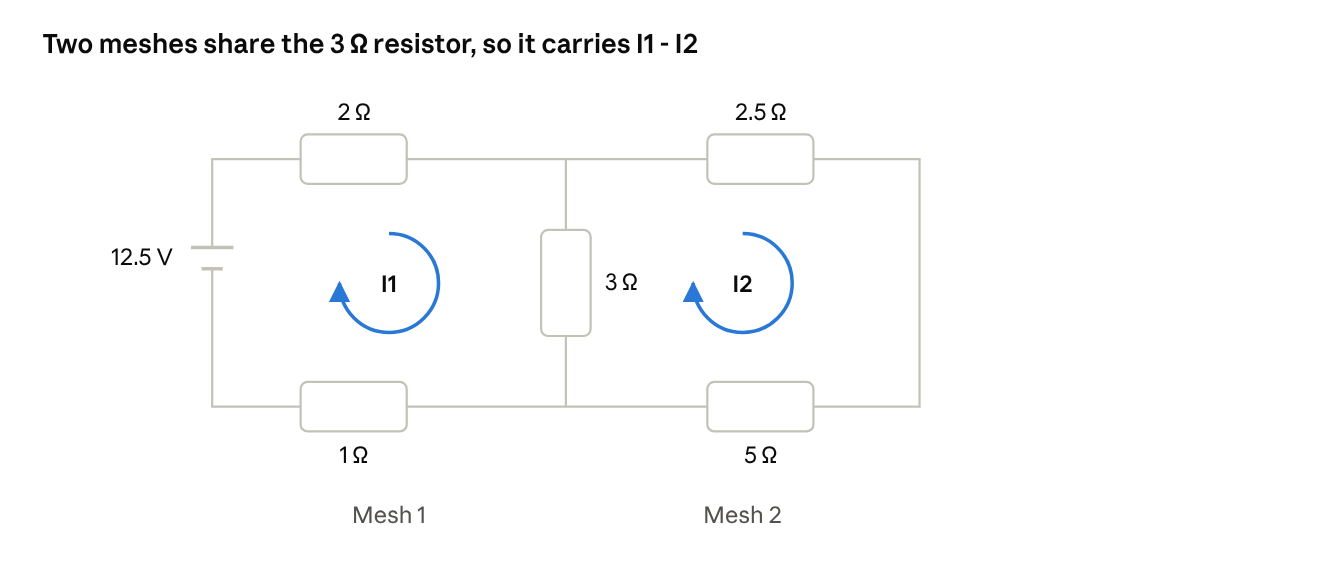
Two meshes. Mesh 1 has 2 Ω, a common 3 Ω, 1 Ω and a 12.5 V source. Mesh 2 has 2.5 Ω, 5 Ω and the common 3 Ω.
Figure 3 · Two-mesh circuit · schematic of example 1Both meshes are taken clockwise, so the common 3 Ω resistor carries I_{1} - I_{2} in mesh 1 and I_{2} - I_{1} in mesh 2.
Solving the two equations gives I_{1} = 2.43\ A and I_{2} = 0.694\ A.
The question asks for the current in the 1 Ω resistor, which belongs only to Mesh 1, so the answer is I_{1} = 2.43\ A, flowing through the 1 Ω resistor from right to left (towards the battery, because the mesh is clockwise). The direction must also be stated, since marks are deducted if it is omitted.
Solved example 2 (3 meshes)
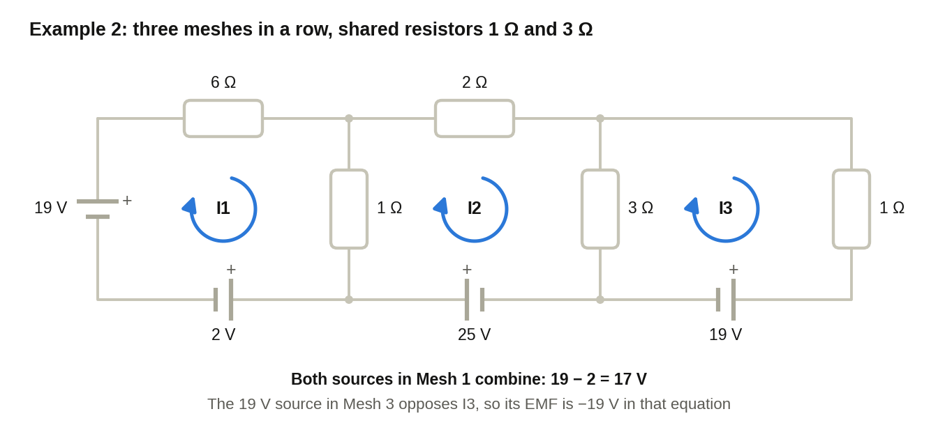
Figure 4 · Three-mesh circuit · schematic of example 2All three mesh currents I_{1}, I_{2} and I_{3} are taken clockwise. The 1 Ω resistor is common to Mesh 1 and Mesh 2, and the 3 Ω resistor is common to Mesh 2 and Mesh 3.
In Mesh 1 the -2 V and +19 V EMFs combine with their signs to give 17.
Solving the equations gives I_{1} = 2.95\ A, I_{2} = 3.65\ A, I_{3} \approx - 2\ A (a negative value only means that the assumed direction was opposite to the actual one; it is not an error).
Solved example 3 (Type 2, with a current source)
Figure 5 · Current source on the outer edge · schematic of example 3The 6 A source sits on the outer edge of Mesh 1, so I_{1} = 6\ A with no KVL. Only Mesh 2 needs a KVL equation, and the 2 Ω resistor is common to both meshes.
Mesh 1 has a 6 A current source in the same direction, so directly I_{1} = 6\ A. KVL for Mesh 2: 5I_{2} + 2\left( I_{2} - I_{1} \right) = - 10, that is 7I_{2} - 2I_{1} = - 10, so I_{2} = 0.2857\ A. If the question asks for the current in the 2 Ω resistor that is common to both meshes, then I_{1} - I_{2} = 6 - 0.2857 = 5.7143\ A (downward, because we took it with respect to I_{1}). If you take I_{2} - I_{1}, the magnitude is the same, only the sign and direction flip. Either choice earns full marks as long as the direction is stated correctly.
Key rule: do not write KVL through a current source
KVL itself still holds everywhere, but the voltage across an ideal current source is unknown, so a KVL equation should not be written through a path that contains a current source. Instead, the larger surrounding path is used (this is called a supermesh). A current source always provides a direct equation.
Figure 6 · Supermesh · current source between two meshesDo not write KVL through the current source. Write one KVL around the dashed outer path (the supermesh) and use the current source value as a direct extra equation.
5Dependent Sources (a common source of errors)
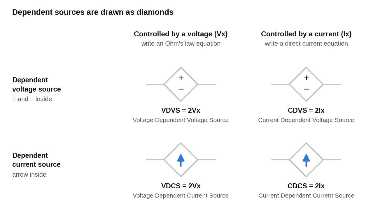
A dependent source is drawn as a diamond. There are two categories:
With plus-minus: dependent voltage source
With an arrow: dependent current source
Each of them has two further types, depending on what it depends on:
Voltage Dependent Voltage Source (VDVS), e.g. 2V_{x}
Current Dependent Voltage Source (CDVS), e.g. 2I_{x}
Voltage Dependent Current Source (VDCS)
Current Dependent Current Source (CDCS)
(The constant need not be 2; it can take any value.)
Figure 7 · Dependent sources · the four typesA source controlled by a voltage needs an equation for that voltage (usually Ohm’s law, or a difference of node potentials), and a source controlled by a current needs a direct current equation.
Which equation to write
Every dependent source is controlled by some other voltage or current in the circuit. The kind of control decides the equation:
A source controlled by a voltage needs an equation expressing it in terms of the unknowns, usually with Ohm's law (V = IR).
A source controlled by a current needs a direct current equation.
Steps: first identify the type of source. Then locate the voltage or current it is controlled by. A common mistake is to start the equation from where the dependent source sits; the equation is written where the controlling voltage or current is, not at the source itself.
Counting equations
As many meshes, as many variables, and as many equations. A dependent source brings an extra unknown (its controlling voltage or current) unless that quantity is already a mesh current or node potential, so it usually needs one extra equation. For example, 3 meshes and 1 dependent source give 4 equations in total. With two dependent sources, you need 2 extra equations. (Exception: if the controlling current is itself a mesh current, for example Ix = I3, no extra equation is needed, as in Section 9.3.)
Example with a dependent voltage source
Suppose there are 2 meshes and one VDVS \left( 2V_{x} \right). Then 3 equations in total:
KVL of the first mesh, where the dependent source value is written as 2V_{x}.
KVL of the second mesh (or the source equation).
Locate the element that V_{x} is measured across. If V_{x} is across a 4 Ω resistor carrying I_{2}, then by Ohm's law V_{x} = 4I_{2}.
Watch the sign: if the plus-minus of V_{x} and your current direction are opposite, you must write V_{x} = - 4I_{2}. Always check sign and direction while writing the dependent source equation; most mistakes happen here.
Important
the sign and value shown in the diagram should not be copied blindly. The equation must carry the sign that follows from the chosen current directions, even where it differs from the diagram.
Example with a dependent current source (VDCS)
A current source behaves like a normal current source, and you cannot go through it (whether dependent or independent). It gives a direct equation, for example I_{1} = 2V_{x}. Then locate where V_{x} is measured and apply Ohm's law. If the current is in the middle branch, two currents flow \left( I_{2} - I_{3} \right); in a corner branch there is a single current. A current that matches the other (same direction) is positive, one that does not match is negative.
A typical exam pattern
A question with 3 meshes and 1 dependent source is a common exam pattern, and it needs 4 equations in total. With two current sources and a CDCS (depending on a current I_{x}), write I_{x} directly in terms of the marked currents (like I_{1}). For example I_{x} = I_{1} - I_{2} (two currents pass through the middle branch). A current-controlled source always gives a direct equation.
Practising at least one numerical on each of the four dependent source types makes the whole topic clear.
6Nodal Analysis in BEE – Worked Examples
What is a node? A point where more than 2 wires are connected (a junction or principal node). Assume potentials V_{A}, V_{B}, V_{C}... at the points. One node is always grounded, and the potential at ground is zero. It is convenient to ground the node that is already at a known potential, or the one with the most branches attached.
Nodal analysis uses KCL: Sum of incoming currents = Sum of outgoing currents. The currents may be assigned any direction.
How to write the currents
A branch current is the potential at the point it flows from, minus the potential at the point it flows to, divided by the resistance. If a battery lies on the path, add the battery's second sign (the sign of the terminal at which the path leaves the battery).
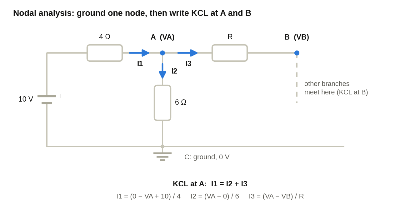
I_{1}: a current going from ground to node A with a 4 Ω resistor and a 10 V battery in between.
In nodal analysis the second sign must always be used. Any consistent convention gives the same answer, but mixing the two conventions is the commonest source of sign errors in nodal analysis. The second-sign rule is a convenient habit: current flows from higher to lower potential, so each branch current is (potential at the start, plus the battery rise on leaving it, minus the potential at the end) divided by R. Using it throughout avoids confusion.
KCL at node A: I_{1} = I_{2} + I_{3} (incoming = outgoing). Then apply KCL at node B as well and solve the two equations.
Figure 8 · Nodal analysis circuit · nodes A, B and ground CGround node C is at 0 V. The currents I_{1}, I_{2} and I_{3} are marked in any direction, and KCL at node A gives I_{1} = I_{2} + I_{3}.
The current source rule in nodal
A current source need not be converted into V/R form; its value is written directly, with a sign according to its direction. (An ammeter and an ideal current source are different things.)
Dependent source in nodal
A dependent source needs an extra equation. For example, if you marked I_{x} as a current \left( I_{4} \right), write I_{x} = I_{4}, then locate the controlling variable of the dependent source and write its equation. If it is controlled by a current, write a direct equation; if by a voltage, use Ohm's law. Use your own marked currents (I_{1}, I_{2}, I_{3}, I_{4}) and do not get confused by I_{x}.
A direct shortcut (N to V_{A}) also exists, but it causes errors in complicated circuits. The safer approach is to go from node to node, from zero toV_{A}, taking the battery's second sign on the way.
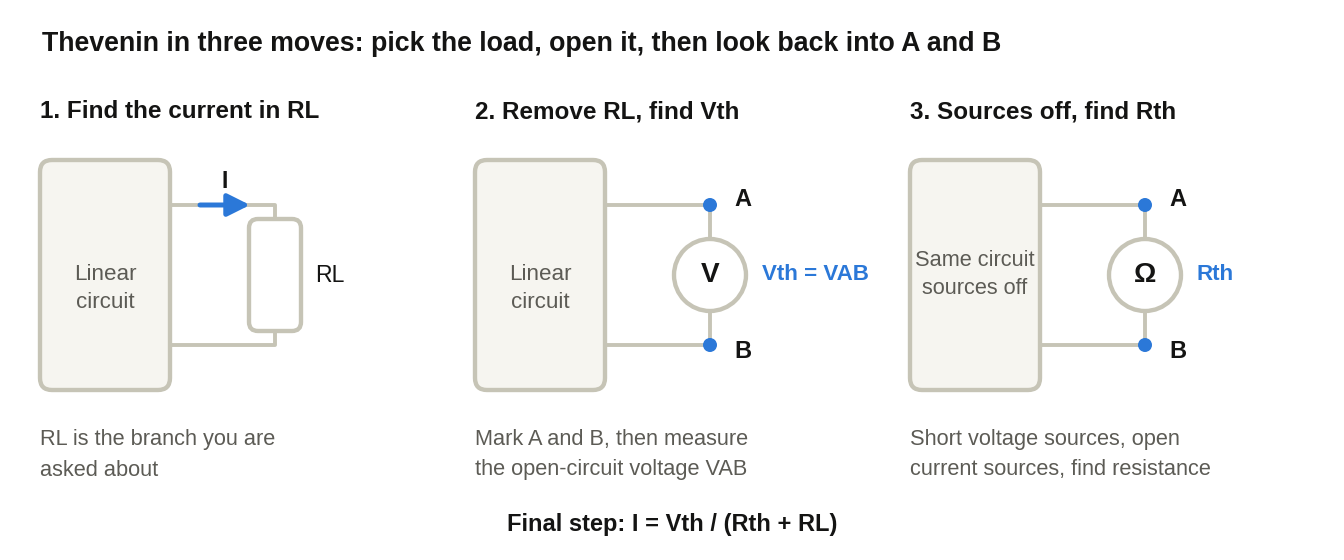
Thevenin's theorem replaces a linear network, as seen from a load, with a single voltage source in series with a resistance. It is applied through a fixed sequence of steps.
Figure 9 · Thevenin procedure · load, open circuit, sources offThe three moves: identify R_{L}, remove it and mark A and B to measure V_{th}, then switch the sources off and look back into A and B to find R_{th}.
Step 1: Identify the load resistance\left( R_{L} \right). The branch in which you must find the current or voltage is the load resistance. For example, if the question says find the current in 4 Ω, then 4 Ω is the load. A household bulb is an everyday example of a resistive load.
Step 2: RemoveR_{L}(open circuit). Removing the bulb leaves an open circuit at that point, while the rest of the circuit stays unchanged. Terminals A and B should always be marked there (a standard convention that saves time and avoids mistakes).
Step 3: Find the Thevenin voltage\left( V_{th} \right). The voltage across the place where you opened the circuit. V_{th} = V_{AB}.
Use a single method: start at A and trace a path to B, along either the left or the right side. For example, from A to C, C to D, D to B: V_{AB} = V_{AC} + V_{CD} + V_{DB}. V_{AC} = I \times R, V_{CD} = battery voltage (with sign), V_{DB} = 0 (where there is no resistor, the voltage is zero).
V_{th} = V_{AB} = V_{AC} + V_{CD} + V_{DB}
Note
take the current in the same direction as the path being traced, and find I using mesh analysis. A negative current is not wrong; it only means the assumed direction was opposite. The same holds for V_{th}: if it comes out as - 5\ V, terminal B is at the higher potential, not A. Carry the sign forward, because it fixes the polarity of the Thevenin source and therefore the direction of the load current. (In a maximum power question only V_{th}^{2} is used, so the sign does not change that answer.)
In the example: I_{1} = \frac{- 5}{8}\ A, so V_{AB} = \left( \frac{- 5}{8} \right) \times 2 + 10 = 8.75\ V. That is V_{th} = 8.75\ V.
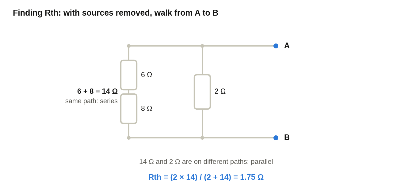
Step 4: Find the Thevenin resistance\left( R_{th} \right). Remove all independent sources: short-circuit the voltage sources and open-circuit the current sources. The diagram stays as it is. Then find the equivalent resistance between A and B. Walk from A to B: resistors on the same path are in series, and resistors on different paths are in parallel. Example: 6 and 8 are in series (14 Ω), and this is in parallel with 2 Ω: R_{th} = 2 \parallel 14 = \frac{2 \times 14}{2 + 14} = 1.75 Ω.
Figure 10 · R_{th}circuit · 2 Ω in parallel with 6 + 8 ΩWith the sources removed, 6 Ω and 8 Ω lie on one path (series). That 14 Ω and the 2 Ω are on different paths between A and B, so they are in parallel.
Step 5: Find the current. The Thevenin equivalent: V_{th} in series with R_{th}, and R_{L} (the one you removed earlier) put back across A-B. By Ohm's law: I = \frac{V_{th}}{R_{th} + R_{L}}.
I = \frac{V_{th}}{R_{th} + R_{L}}
7.2 Norton's Theorem
The steps in Norton are almost the same, with a small difference:
Step 1: Identify R_{L}.
Step 2: In Thevenin you opened R_{L}; in Norton you short-circuitR_{L}.
Step 3: In Thevenin you found V_{th}; in Norton you find the Norton current\left( I_{N} \right), the current in the branch where R_{L} was. I_{N} comes out of mesh analysis (like I_{1} - I_{2}).
Step 4: R_{N} = R_{th}; both values are the same and the procedure is the same (voltage source short, current source open). The only difference is that here R_{L} is opened, not shorted.
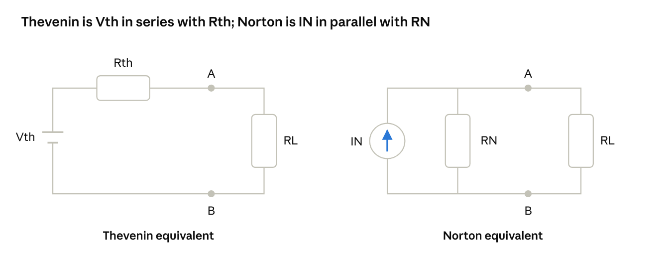
Step 5: In the Norton equivalent, the current sourceI_{N}is in parallel withR_{N} (in Thevenin the voltage source was in series). Put R_{L} back. By the Current Divider Rule: I_{L} = I_{N} \times \frac{R_{N}}{R_{N} + R_{L}}.
Figure 11 · Thevenin and Norton equivalent circuitsThevenin replaces the circuit with V_{th} in series with R_{th}, Norton with I_{N} in parallel with R_{N}; R_{L} goes back across A and B in both.
Exam example: "Find the voltage drop across 3 Ω." That means find the current and then use V = I \times R. The Norton theorem does not give voltage directly, it gives current. R_{L} = 3\ \Omega. First short R_{L}; the current flowing there is I_{N} (three mesh equations and one supermesh equation, from which I_{3} is obtained). Then find R_{N} and apply the formula.
Norton is comparatively easier than Thevenin, because in Norton you need a current, which comes out of mesh analysis, while in Thevenin students tend to get stuck on V_{th}.
7.3 Maximum Power Transfer Theorem
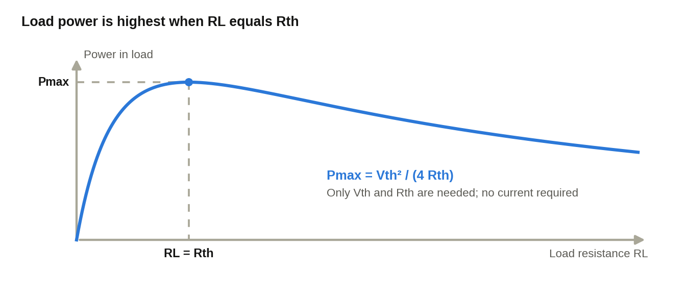
Condition: the load resistance equals the Thevenin resistance.
Figure 12 · Maximum power transfer · power versus load resistanceLoad power rises, peaks exactly where R_{L} equals R_{th}, and then falls again as R_{L} keeps growing.
Derivation:P = I^{2}R_{L}, and from Thevenin I = \frac{V_{th}}{R_{th} + R_{L}}. Under the maximum power condition R_{L} = R_{th}, so replacing R_{th} by R_{L} makes the denominator \left( 2R_{L} \right)^{2}, hence P_{\max} = \frac{V_{th}^{2}}{4R_{L}}. So in a Max Power numerical you only need V_{th} and R_{th}, there is no need to find the current; find P_{\max} directly.
Proof of the condition RL = Rth (needed when the question says "prove"): The derivation above assumes RL = Rth; it only gives Pmax. To prove the condition itself, write P = Vth²·RL / (Rth + RL)² and differentiate with respect to RL: dP/dRL = Vth²·[(Rth + RL)² − 2RL(Rth + RL)] / (Rth + RL)⁴ = Vth²·(Rth − RL) / (Rth + RL)³. Setting dP/dRL = 0 gives RL = Rth. For RL < Rth the slope is positive and for RL > Rth it is negative, so this is a maximum (not a minimum). Substituting RL = Rth then gives Pmax = Vth²/(4Rth).
7.4 Thevenin/Norton with dependent sources
When a dependent source (diamond) is present, the formula forR_{th}is different:R_{th} = \frac{V_{th}}{I_{N}}. In the independent-source case you removed the sources to find R_{th}, but with a dependent source that does not work.
R_{th} = \frac{V_{th}}{I_{N}}
Steps (Thevenin, with a dependent source):
Open R_{L} and mark A, B.
Find V_{th} (open-circuit voltage). In a path where no current flows, the voltage drop is zero, so V_{th} is obtained directly. Use mesh equations and the dependent source equation.
Find I_{N}: put a short circuit in place of R_{L} and find the current (from mesh analysis). Here you can write two mesh equations, one dependent source equation and one for I_{N}, four equations in total.
R_{th} = \frac{V_{th}}{I_{N}}.
Nothing separate needs to be learned for Norton, because R_{N} = R_{th} anyway. The only difference is that in Thevenin you find V_{th} first and then R_{th}, and here the order can be reversed, but in the end you need both quantities. Several methods exist for circuits with dependent sources; this is the simplest. Caution: Rth = Vth/IN works only when the network also contains an independent source. If the network has only dependent sources, Vth = 0 and IN = 0, so the ratio is 0/0; use the test-source method (Section 9.2) instead.
Note
Thevenin's theorem with dependent sources has often been asked in previous years' papers and deserves dedicated practice.
7.5 Superposition and Tellegen
Questions on the superposition theorem are commonly asked. Tellegen's theorem is in the syllabus but has rarely been asked in previous years; still, it can appear as a surprise question, so keep at least the basic idea ready.
8Tricky Conceptual and Short-Answer Questions (2 to 4 Marks)
Short-answer questions carry only two to four marks each, but they are where well-prepared students pull ahead. Each question below comes with the concept behind it and the way to present it in the answer sheet.
8.1 Why can the Superposition Theorem not be used to calculate power directly?
Concept: Superposition applies strictly to linear relationships, that is, relationships where f\left( x_{1} + x_{2} \right) = f\left( x_{1} \right) + f\left( x_{2} \right). Voltage and current in a linear circuit satisfy this, but power does not. Power is a quadratic quantity (P = I^{2}R or P = \frac{V^{2}}{R}), so it is non-linear in the source values.
Exam tip
Show it with a simple two-source example. If the two sources, acting one at a time, produce currents I_{1} and I_{2} (in the same direction) in a resistor R, the total power is not the sum of the two individual powers:
For example, take R = 2\ \Omega, I_{1} = 1\ A and I_{2} = 2\ A. Then P_{1} = 2\ W and P_{2} = 8\ W, so P_{1} + P_{2} = 10\ W. The actual current is 3\ A, which gives P = 3^{2} \times 2 = 18\ W. The missing 8 W is the cross term 2I_{1}I_{2}R.
The correct procedure is to apply superposition to the voltage or current first, add the results with their signs, and only then calculate the power from the total.
8.2 Source transformation and ideal source equivalence
Practical versus ideal sources:
An ideal voltage source keeps a fixed terminal voltage whatever current is drawn; its internal resistance is zero (R_{s} = 0).
An ideal current source delivers a fixed current whatever the terminal voltage; its internal resistance is infinite (R_{s} = \infty).
A practical voltage source is an ideal source V_{s} in series with a resistance R_{s}, so its terminal voltage falls as the load current rises: V = V_{s} - IR_{s}.
A practical current source is an ideal source I_{s} in parallel with a resistance R_{s}, so part of I_{s} is diverted through R_{s} as the terminal voltage rises.
A practical voltage source and a practical current source are equivalent when they have the same R_{s} and:
V_{s} = I_{s}R_{s}
Why an ideal voltage source cannot be transformed: With R_{s} = 0, the equivalent current would be I_{s} = \frac{V_{s}}{R_{s}}, which tends to infinity. No finite current source can reproduce this, so an ideal voltage source has no finite, conventional Norton equivalent. By the same argument, an ideal current source (R_{s} = \infty) would need V_{s} = I_{s}R_{s} \rightarrow \infty, so it has no finite, conventional Thevenin equivalent either. Source transformation works only for practical sources, which always have a finite, non-zero R_{s}.
8.3 Tellegen's Theorem: why it holds for every kind of element
Tellegen's theorem states that in any lumped network with b branches, the sum of the powers absorbed by all the branches is zero. In terms of the branch voltages v_{k} and branch currents i_{k} (taken in associated reference directions):
\sum_{k = 1}^{b}v_{k}i_{k} = 0
Why it holds for linear, non-linear, time-invariant, active or passive elements: The proof uses only the network topology, through two laws: KVL for the branch voltages and KCL for the branch currents. It never uses the relationship between v_{k} and i_{k} inside an element, so the nature of the element does not matter. Writing each branch voltage as a difference of node potentials, the sum reduces to node potentials multiplied by the algebraic sum of currents at each node, and KCL makes every such sum zero.
This is the conservation of energy principle in circuit form: the power delivered by the sources equals the power absorbed by the rest of the network.
8.4 Reciprocity Theorem: statement and conditions
Statement: In a linear, bilateral network with a single excitation source, if a source V placed in one branch produces a current I in another branch, then the same source V placed in the second branch produces the same current I in the first. The ratio \frac{V}{I}, called the transfer resistance, is the same in both directions.
Essential conditions:
Only a single excitation source acts in the network.
The network must be linear.
The elements must be passive and bilateral (resistors, inductors and capacitors).
No dependent sources are present. Circuits with dependent sources are generally non-reciprocal, so the theorem cannot be assumed there, and it fails for non-bilateral elements such as diodes and transistors.
Four numerical patterns appear again and again in Unit 1. For each one, the problem type, the usual data and the method are given below, so that the steps become automatic in the exam.
9.1 Bridge circuit with star-delta reduction
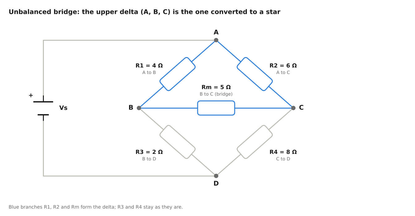
Problem type: An unbalanced Wheatstone bridge connected across a DC voltage source V_{s}. Because the bridge branch carries current, the circuit cannot be reduced by simple series-parallel steps; a delta or a star must be converted first.
Typical values: The source is connected between A (positive) and D. Top branches: R_{1} = 4\ \Omega (A to B) and R_{2} = 6\ \Omega (A to C). Bridge branch: R_{m} = 5\ \Omega (B to C). Bottom branches: R_{3} = 2\ \Omega (B to D) and R_{4} = 8\ \Omega (C to D).
Figure 13 · Unbalanced Wheatstone bridge · upper delta A-B-CThe branches R_{1}, R_{2} and R_{m} (blue) form the upper delta between A, B and C. Converting it into a star removes the bridge branch and leaves only series-parallel combinations.
Question:
Convert the upper (or lower) delta into an equivalent star.
Determine the total equivalent resistance R_{eq} seen by the DC source.
Calculate the total source current and the current through the middle 5\ \Omega branch.
Solution outline:
The delta sides are R_{AB} = 4\ \Omega, R_{CA} = 6\ \Omega and R_{BC} = 5\ \Omega, with a sum of 15\ \Omega. Each star arm is the product of the two adjacent delta sides divided by this sum:
Let the star centre be N. The arm R_{B} is in series with R_{3} (1.333 + 2 = 3.333\ \Omega) and the arm R_{C} is in series with R_{4} (2 + 8 = 10\ \Omega). These two paths are in parallel: 3.333 \parallel 10 = 2.5\ \Omega.
The total resistance is R_{eq} = R_{A} + 2.5 = 1.6 + 2.5 = 4.1\ \Omega, and the source current is I = \frac{V_{s}}{4.1} \approx 0.244\, V_{s}.
The star hides R_{m}, but nodes A, B and C are unchanged, so their voltages are still valid. The current I splits at N in the ratio of the two paths, giving 0.75I through the B path and 0.25I through the C path. Then V_{N} - V_{B} = 0.75I \times 1.333 = I and V_{N} - V_{C} = 0.25I \times 2 = 0.5I, so V_{C} - V_{B} = 0.5I.
Return to the original circuit: I_{m} = \frac{V_{C} - V_{B}}{5} = \frac{0.5I}{5} = 0.1I = \frac{V_{s}}{41}, flowing from C to B. For example, a 41\ V supply gives I = 10\ A and I_{m} = 1\ A.
Exam note
The current in the middle branch must be found in the original circuit, using the node voltages. The star-equivalent circuit has no R_{m} branch to read it from.
9.2 Thevenin's equivalent with dependent sources (test source method)
Problem type: A circuit containing both an independent source and a dependent source, with the load resistance R_{L} connected across terminals A-B.
Standard pattern: The circuit contains a 10\ V independent voltage source, a resistor and either a Current Dependent Voltage Source (CDVS) or a Voltage Dependent Current Source (VDCS).
Method 1: open-circuit and short-circuit tests
Remove R_{L} and find the open-circuit voltage across A-B: V_{oc} = V_{th}.
Independent source removal fails to give R_{th} when a dependent source is present, so short A-B and find the short-circuit current I_{sc} = I_{N}.
Compute the Thevenin resistance:
R_{th} = \frac{V_{oc}}{I_{sc}}
Method 2: test source. Deactivate only the independent sources (short the voltage sources, open the current sources) and leave every dependent source in place, since it is controlled by the circuit and stays active. Connect a virtual 1\ V or 1\ A test source across A-B and compute:
R_{th} = \frac{V_{test}}{I_{test}}
Both methods are acceptable. Section 7.4 gives the underlying idea.
9.3 Supermesh with three loops and an internal dependent source
Problem type: Three meshes sharing branches. Mesh 1 and Mesh 2 share a branch containing a dependent current source (for example i = 2I_{x}), and I_{x} is a current flowing in an outer branch of Mesh 3.
Question and method:
Form the constraint equation between I_{1} and I_{2} using the branch source: I_{1} - I_{2} = 2I_{x}, with the sign set by the direction of the source relative to the mesh currents (in the Section 4 figure the source points upward, giving I2 − I1 = IS; here the source is taken to point downward, giving I1 − I2; the sign always follows the source arrow). The outer branch of Mesh 3 belongs to Mesh 3 alone, so I_{x} = I_{3} (again with the sign from its direction), and the constraint becomes I_{1} - I_{2} = 2I_{3}.
Write one unified KVL equation around the outer path enclosing Mesh 1 and Mesh 2 (the supermesh), leaving out the branch that holds the current source.
Write the standard KVL equation for Mesh 3, taking care with the branches it shares with the other two meshes.
Solve the three simultaneous equations for I_{1}, I_{2} and I_{3}.
Because I_{x} is itself a mesh current, the dependent source does not add a fourth equation here. If it were controlled by a voltage, an extra Ohm's law equation would be needed (see Section 5).
9.4 Maximum power transfer with fixed internal source resistance
Problem type: A DC circuit with several fixed resistors and an adjustable load resistor R_{L}.
Standard task:
Disconnect R_{L} and compute V_{th} and R_{th} across its connection points.
State the condition for maximum power transfer: R_{L} = R_{th}.
Calculate the maximum power: P_{\max} = \frac{V_{th}^{2}}{4R_{th}}.
Calculate the efficiency \eta at maximum power and show that it is 50%.
Proof that\eta = 50\%: The same current I flows through R_{th} and R_{L}, so at R_{L} = R_{th} the load receives exactly half of the power the source delivers:
This 50% refers to the Thevenin equivalent circuit. It is why maximum power transfer suits low-power signal circuits, while power systems are designed for high efficiency instead.
10BEE Unit 1 Important Formulas (Quick Reference)
Revise this table the night before the exam. It collects the relations used throughout Unit 1.
Topic
Key relation / formula
KCL and KVL
\sum I_{in} = \sum I_{out} (at any node)
\sum V_{drop} = \sum EMF (around any closed loop)
Supermesh constraint
I_{a} - I_{b} = \pm I_{source} (the sign follows the direction of the current source)
R_{th} = \frac{V_{oc}}{I_{sc}} or R_{th} = \frac{V_{test}}{I_{test}}
Maximum power transfer
Condition: R_{L} = R_{th}
P_{\max} = \frac{V_{th}^{2}}{4R_{th}} (DC circuits), with \eta = 50\%
Star-delta convention:R_{A}, R_{B} and R_{C} are the star arms at nodes A, B and C, and R_{AB}, R_{BC} and R_{CA} are the delta sides between those nodes. Each star arm is the product of its two adjacent delta sides divided by the sum of all three; each delta side is the sum of its two adjacent star arms plus their product divided by the opposite arm.
11DTU BEE Exam Preparation Tips
Going by previous years' papers, expect one question from Mesh/Nodal and one from Theorems in Unit 1. Thevenin, Norton and Max Power Transfer are linked, so prepare all three together.
Practise numericals on dependent sources, since Thevenin questions with dependent sources have often appeared in previous years.
For dependent sources: controlled by a voltage = express it using Ohm's law or node potentials, controlled by a current = direct equation.
Do not write a mesh KVL through a current source (its voltage is unknown). Use a supermesh.
In mesh keep one sign convention; in nodal always use the second sign.
In Thevenin always mark A and B, and use a single method (walk from A to B) for V_{th}.
Max power: find V_{th} and R_{th}, then P_{\max} = \frac{V_{th}^{2}}{4R_{th}}.
State the direction of the current (for example upward or downward); marks are deducted if it is missing.
Learn the scientific calculator's equation-solving mode, redraw the diagram at every step, and practise regularly.
Where students lose marks in Unit 1
Writing a mesh KVL through a current source instead of using a supermesh.
Finding Rth by switching off sources when a dependent source is present.
Adding powers in Superposition instead of adding currents or voltages.
Mixing sign conventions between meshes, or forgetting the current direction in the final answer.
Not redrawing the circuit after switching off each source.
12Repeated DTU Exam Questions (Practice Set)
Five commonly reported question types from DTU Mid-Sem and End-Sem papers. Each question lists the problem statement, the given data, and the tasks to be solved.
Source note: the exam years and the grading-pattern tips in this document are student-compiled and were not independently verified. Please check them against the official previous-year papers and your instructor’s guidance. These are practice problems, not verified previous-year questions. The circuit details and worked solutions given for Q1, Q4 and Q5 are reconstructed for practice and may differ from the figures in the original papers, so always follow the figure in the actual paper.
Q.
Topic
Reported Appearances
Marks
Q1
Mesh Analysis
Mid-Sem / End-Sem 2022, 2024
—
Q2
Thevenin’s Theorem
Mid-Sem 2023, End-Sem 2025
—
Q3
Maximum Power Transfer
End-Sem 2021, 2023
4 + 6
Q4
Nodal Analysis
Mid-Sem 2022, 2024
—
Q5
Superposition Theorem
Mid-Sem 2021, 2025
—
Q1
Mesh Analysis with Internal Current Source (Supermesh)
Reported as repeated in DTU Mid-Sem / End-Sem 2022, 2024
Problem Statement
In the circuit shown, three meshes share elements. Mesh 1 and Mesh 2 share a branch carrying a common independent current source of 2 A directed upwards.
Mesh 1: 20 V independent voltage source and a 4 Ω resistor.
Common branch (Mesh 1 & Mesh 2): 2 A current source, directed upwards.
Mesh 2: upper-branch resistor of 6 Ω.
Common branch (Mesh 2 & Mesh 3): resistor of 2 Ω.
Mesh 3: 5 Ω resistor and an opposing 10 V DC voltage source.
Tasks
Identify the supermesh path and write its constraint equation.
Formulate KVL around the supermesh and around Mesh 3.
Determine the branch current through the 2 Ω shared resistor between Mesh 2 and Mesh 3.
Show circuit details and worked solution
Circuit: Mesh 1 (left) has the 20 V source (+ terminal on top) in its left branch and a 4 Ω resistor in its top branch. The shared branch of Mesh 1 and Mesh 2 holds the 2 A current source, pointing upward. Mesh 2 (middle) has the 6 Ω resistor in its top branch and a plain wire at the bottom. The shared branch of Mesh 2 and Mesh 3 holds the 2 Ω resistor. Mesh 3 (right) has a plain top wire, and its right branch has a 5 Ω resistor in series with the 10 V source, with + at the top and − at the bottom, so it opposes the clockwise current I3.
Constraint: Take all mesh currents clockwise. The shared branch carries I1 downward and I2 upward, so I2 − I1 = 2 A, that is I1 = I2 − 2.
Answer: Current in the shared 2 Ω resistor = I2 − I3 = 3.0 A, flowing downward.
Q2
Thevenin’s Theorem with a Dependent Source
Reported as repeated in DTU Mid-Sem 2023, End-Sem 2025
Problem Statement
Find the Thevenin equivalent circuit across terminals A–B for the following network.
Independent voltage source Vs = 24 V in series with R1 = 6 Ω.
Voltage-dependent current source (VDCS) between node C and ground: id = 0.5 Vx, directed downwards.
Resistor R2 = 12 Ω connects node C to terminal A.
Controlling voltage Vx is the drop across the 6 Ω series resistor: Vx = Vs − VC.
Terminals A and B are open.
Tasks
Find the open-circuit Thevenin voltage Vth = VAB.
Explain why turning off the sources does not directly yield Rth when a dependent source is present.
Determine the short-circuit (Norton) current Isc across A–B and calculate Rth = Vth / Isc.
Find the current delivered to an external load RL = 4 Ω connected across A–B.
Q3
Maximum Power Transfer: Derivation and Numerical
Reported as repeated in DTU End-Sem 2021, 2023
Part A: Derivation (4 Marks)
Tasks:
Prove that maximum power is transferred from a linear active bilateral DC network to a variable resistive load RL when RL = Rth.
Prove that the efficiency under this condition is 50%.
Part B: Numerical (6 Marks)
An unbalanced Wheatstone bridge has the following arms, with a supply of V = 18 V across the bridge input terminals. A variable load RL is connected between the bridge junctions C and D.
Left upper arm: R1 = 3 Ω; left lower arm: R3 = 6 Ω.
Right upper arm: R2 = 6 Ω; right lower arm: R4 = 2 Ω.
Calculate:
The value of RL for maximum power absorption.
The maximum power Pmax delivered to RL.
Q4
Nodal Analysis with Supernode
Reported as repeated in DTU Mid-Sem 2022, 2024
Problem Statement
For the circuit with nodes 1, 2 and ground (node 0):
An ideal 12 V voltage source is connected directly between node 1 and node 2 (positive terminal at node 1).
Node 1 is connected to ground through a 4 Ω resistor and receives 3 A from an independent current source.
Node 2 is connected to ground through a 6 Ω resistor, and to another branch with a 2 Ω resistor in series with a 4 V battery.
Tasks
Identify the supernode and write its constraint equation (V1 − V2 = 12 V).
Formulate the combined KCL equation for the supernode.
Solve for the node potentials V1 and V2, and calculate the power dissipated in the 4 Ω resistor.
Show circuit details and worked solution
Circuit: The bottom wire is ground (node 0). A 4 Ω resistor connects node 1 to ground, and the 3 A current source drives current into node 1. The ideal 12 V source lies between node 1 (+) and node 2 (−). A 6 Ω resistor connects node 2 to ground, and a second branch from node 2 to ground has the 2 Ω resistor in series with the 4 V battery, whose + terminal is on the node 2 side.
Supernode constraint: V1 − V2 = 12 V.
KCL at the supernode (currents leaving = 3 A entering): V1/4 + V2/6 + (V2 − 4)/2 = 3. Multiplying by 12 gives 3V1 + 8V2 = 60.
Solution: Substituting V1 = V2 + 12 gives 11V2 = 24, so V2 = 24/11 ≈ 2.18 V and V1 ≈ 14.18 V.
Power in the 4 Ω resistor: P = V1²/4 ≈ 50.28 W.
Q5
Superposition Theorem Verification
Reported as repeated in DTU Mid-Sem 2021, 2025
Problem Statement
A circuit has three independent energy sources and three resistors.
Source 1: V1 = 30 V DC voltage source.
Source 2: I1 = 4 A DC current source.
Source 3: V2 = 10 V DC voltage source.
Resistors: R1 = 5 Ω, R2 = 10 Ω, R3 = 2 Ω.
Tasks
Find the current I through R2 with each source acting alone (short-circuit voltage sources, open-circuit current sources).
Verify that the algebraic sum of the individual currents equals the total current when all sources act simultaneously.
State whether the total power in R2 can be found by summing the powers from each individual case, with mathematical reasoning.
Show circuit details and worked solution
Circuit: Three branches connect a central node Vx to ground. Left: the 30 V source (+ on top) in series with R1 = 5 Ω. Centre: R2 = 10 Ω to ground, with the 4 A current source injecting current into the central node. Right: R3 = 2 Ω in series with the 10 V source, whose + terminal is at ground, so the far end of R3 sits at −10 V. The current I in R2 is taken downward, I = Vx/10.
30 V source alone (4 A source open, 10 V source shorted): (Vx − 30)/5 + Vx/10 + Vx/2 = 0, so Vx = 7.5 V and I′ = 0.75 A (downward).
4 A source alone (both voltage sources shorted): 5 ∥ 10 ∥ 2 = 1.25 Ω, so Vx = 4 × 1.25 = 5 V and I″ = 0.50 A (downward).
10 V source alone (30 V source shorted, 4 A source open): Vx/5 + Vx/10 + (Vx + 10)/2 = 0, so Vx = −6.25 V and I‴ = −0.625 A.
Total current: I = 0.75 + 0.50 − 0.625 = 0.625 A (downward). This matches the direct solution with all sources acting, which gives Vx = 6.25 V.
Power: The actual power in R2 is (0.625)² × 10 = 3.906 W, but the individual powers add up to 5.625 + 2.5 + 3.906 = 12.03 W. The two differ, so power cannot be found by summing the powers of the individual cases.
Exam Answer-Sheet Presentation Strategy
Based on the DTU grading pattern as reported by students; confirm with your course instructor
Guideline
What to do
Redraw the circuit at every step
In Thevenin and Superposition problems, draw a fresh sub-circuit after switching off each source. Writing the formula directly without the redrawn circuit costs step marks.
Mark arrow directions on shared branches
For shared resistors, always label polarities (±) and the net assumed direction explicitly, e.g. (I1 − I2).
Units and final highlight
Box every final answer with its unit, and state the direction where relevant, e.g. IL = 1.85 A, from A to B.
13Frequently Asked Questions (FAQ)
What is covered in DTU BTech 1st year BEE Unit 1?
Unit 1 covers DC circuits: mesh analysis, nodal analysis and network theorems (Thevenin, Norton, Maximum Power Transfer and Superposition). Tellegen's theorem is in the syllabus but has been asked rarely. Always confirm the current list on the official DTU website.
What is the condition for maximum power transfer in a DC circuit?
Maximum power is transferred to the load when RL equals Rth. The maximum power is Pmax = Vth² / (4 Rth) and the efficiency at that point is 50%.
How do you find Rth when a circuit has a dependent source?
Turning off the sources does not work directly, because the dependent source stays active. Use Rth = Voc / Isc (open-circuit voltage divided by short-circuit current), or apply a test source and use Rth = Vtest / Itest.
When should I use a supermesh or a supernode?
Use a supermesh when a current source is shared between two meshes, and a supernode when an ideal voltage source connects two non-reference nodes. Both avoid writing an equation through a source whose voltage or current is unknown.
Why can't the Superposition Theorem be used to add powers directly?
Superposition holds only for linear quantities such as voltage and current. Power is quadratic (P = I²R), so the total power is not the sum of the powers from each source acting alone; cross-product terms appear. In Q5 below, the individual powers add up to about 12.03 W, while the actual power in R2 is about 3.91 W.
What is the difference between BEEE and BEE?
BEE is Basic Electrical Engineering, and BEEE is Basic Electrical and Electronics Engineering. The first units (DC circuits, AC circuits, three-phase systems) are similar, and BEEE usually adds an electronics section. Check your own syllabus.
Aur notes aur strategies chahiye?
Daily Spark ki WhatsApp community join karein: B.Tech notes, exam strategies aur new articles sabse pehle wahin milte hain.